Fabric Expansion Joint
Fabric expansion joints are flexible connectors designed to provide stress relief in ducting systems by absorbing movement caused by thermal changes.
They also act as vibration isolators, shock absorbers and, in some instances, make up for minor misalignment of adjoining ducting or equipment. Fabric expansion joints may also be known as “compensators”.
They are fabricated from a wide variety of materials, including synthetic elastomers, fabrics, insulation materials and fluoroplastics, dependent upon the design.
The designs range from a single ply to complex, multi-ply constructions attached to metal frames for operation under extremes of temperature or corrosion.
Since their introduction, expansion joints have been used to solve an increasing range of flexible sealing challenges.
However, the major application is in power generation. As materials have been developed and the technology of expansion joint design have been improved, they have been used successfully in a much wider variety of industrial
applications, including:
• Cement
• Chemical
• Heating and ventilation
• Marine and offshore
• Metal Foundries
• Petrochemical
• Power generation
- Co-generation
- Fossil Fuel
- Gas Turbine
- Nuclear
• Pulp and paper
• Steel and aluminium
• Waste incineration
Expansion joints provide flexibility in ductwork and are used to allow for 4 main situations:
1. Expansion or contraction of the duct due to temperature changes
2. Isolation of components to minimize the effects of vibration or noise
3. Movement of components during process operations
4. Installation or removal of large components, and erection tolerances
The benefits of fabric expansion joints include:
• Ability to absorb simultaneous movements easily in more than one plane – this allows the duct designer to accommodate composite movements in fewer (and simpler) expansion joints
• Very low forces required to move the expansion joint – the low spring rate enables their use to isolate stresses on large, relatively lightweight, equipment. A particular example is a gas turbine exhaust, where it is crucial to minimize the forces from the duct expansion on the turbine frame
• Corrosion resistant materials of construction – modern technology materials enable the use in aggressive chemical conditions
• Noise and vibration resistance – fabric expansion joints provide a high degree of noise isolation and vibration damping Ease of installation and maintenance
• Minimal replacement cost – the fabric of the expansion joint assembly can be replaced simply and economically
• Design freedom – fabric expansion joints can be tailored to suit the duct application, with taper, transition, or irregular shape, so allowing the designer the maximum variety of options
• Thermal breaks – self-insulating properties of the fabric allow simple hot-to-cold transition
There are 2 basic forms of construction, dependent upon the number of layers in the expansion joint:
1. Single layer construction
They are suitable solutions for low temperature and low saturated environments. It is made of silicone, PTFE, etc. elastomer reinforced fabrics. Flange reinforcement is given to the edges of the compensator fabric to ensure
flange sealing, in addition, PTFE gaskets are recommended for environments with aggressive chemicals. In this way, a good sealing is prevented from damaging the compensator of the connecting elements.
2. Multi-layer construction
In multi-layer compensators, it is aimed to achieve working performance suitable for ambient conditions by combining fabrics with different properties.
The usage purposes of compensator fabric layers from outer layer to inner layer is roughly follows as ;
1. Outer Layer: Protects the compensator against external factors (UV, acid, water, dirt, etc.). The elastomer coated fabric to be used in this layer protects the sealing layer in a lower layer against impacts
and contributes to the sealing according to the type of elastomer. If 100% gas tight Laminated PTFE Glass fiber fabric is used in this layer, the use of the lower sealing layer is not required.
2. Sealing Layer: Provides fluid sealing and ensures safe operation of compensator layers and line.
3. Heat Insulation Layer: It protects the layers on it from the high temperature of the fluid and at the same time ensures that the outer surface temperature of the compensator cloth is reduced to suitable
temperatures for worker safety.
4. Strength Layer: This layer provides resistance against;
a. Sudden pressure changes (pulsation)
b. Vibrations (vibrations)
c. Line movements (extension, compression, lateral shear, torsion, bending)
thus, increases the service life of the compensator.
There are 3 types of clamping configurations, each of which may employ either of the above constructions:
1) Belt type expansion joint configuration
2) Flanged expansion joint configuration
3) Combination type expansion joint configuration
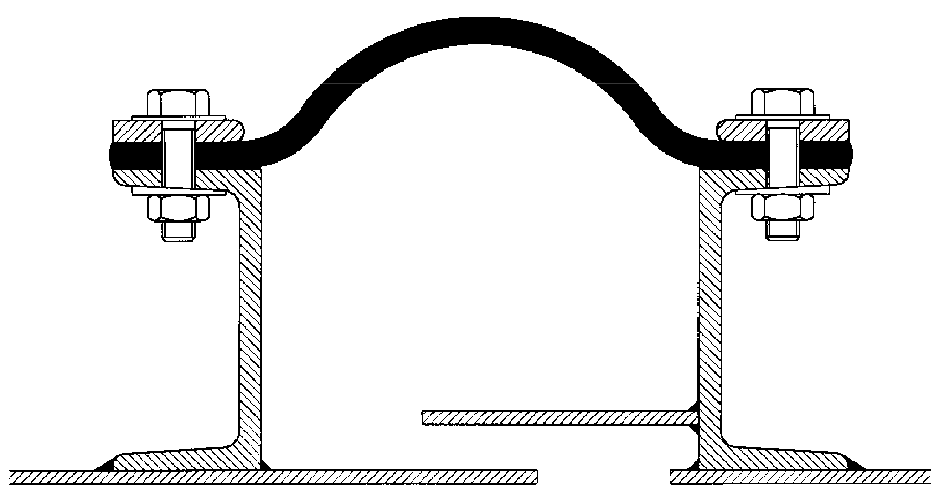
Belt type expansion joint configuration
An expansion joint in which the flexible element is made like a flat belt.
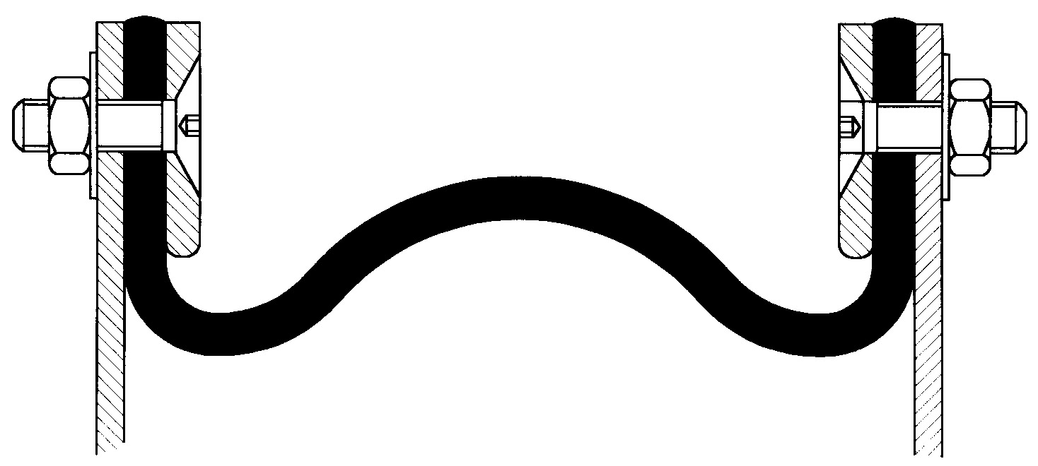
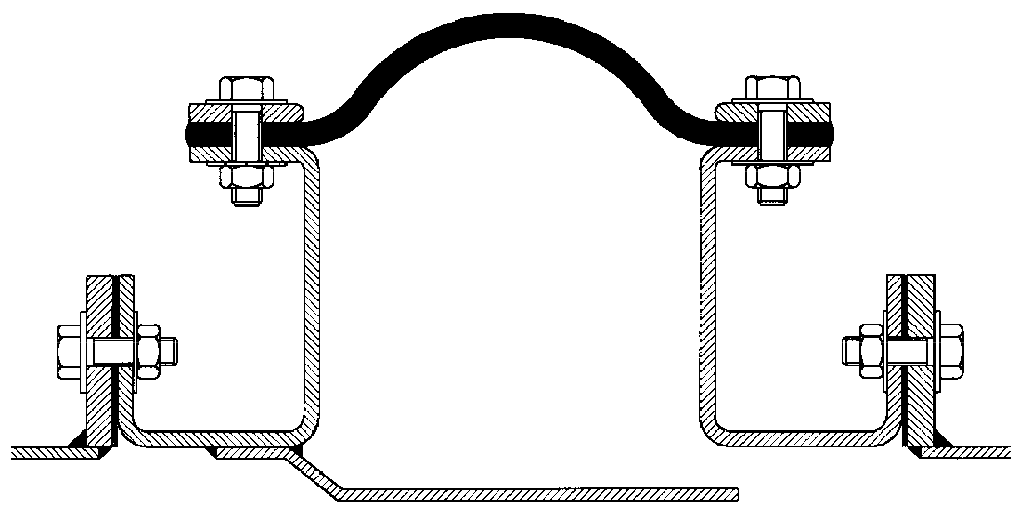
Flanged expansion joint configuration
An expansion joint in which the flexible element has flanges formed at right angles.
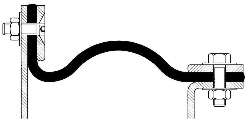
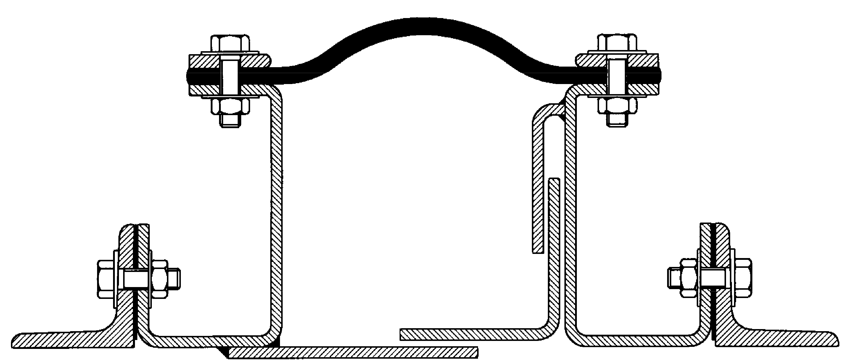
Combination type expansion joint configuration
An expansion joint which utilises both belt type and flanged configurations.
Ambient temperature
An expansion joint should not be in an area of poor air circulation, or subject to high temperature radiation. Fabric expansion joints working at elevated temperatures (above 250°C) depend upon a temperature gradient across the
joint. This gradient is the difference between the high internal temperature (hot face) and colder external temperature (cold face) of the joint. High ambient temperatures in the vicinity of the joint will reduce this
temperature gradient reducing the rate at which heat can be radiated from the external surface of the joint. This in turn will lead to failure of the primary seal (i.e. PTFE membrane) and hence the joint. Therefore, it is
important to ensure that adequate provision is made to keep local ambient temperatures within manufacturer’s recommendations, and external lagging or insulating of joints is generally not allowed. Where cold external ambient
conditions prevail, due consideration should be given to the possibility of condensation forming inside fabric expansion joints. Counter measures such as internal or external insulation may be considered appropriate.
Environment
Fabric expansion joints are very often situated in arduous industrial locations such as power generation plants, chemical works, cement plants etc. In such locations, they may be subjected to higher than normal levels of
pollutants, some of which may contain aggressive agents, with possible attack to the elastomer outer cover of the joint. If the type and concentration of such pollutants is known at the design stage, it is possible to design a
joint which will resist such attack by selection of an appropriate outer cover, resistant to specific agents.
Location
Whether a joint is located internally within a building or outside and exposed to the elements may also have a bearing on the selection of the type of outer cover. Internally located joints may not necessarily require waterproof
outer covers.
Bolt loading guide (valid for MoS2-lubricated bolting) used to achieve flue gas tightness (TI-002) or nekal tightness (TI-003).
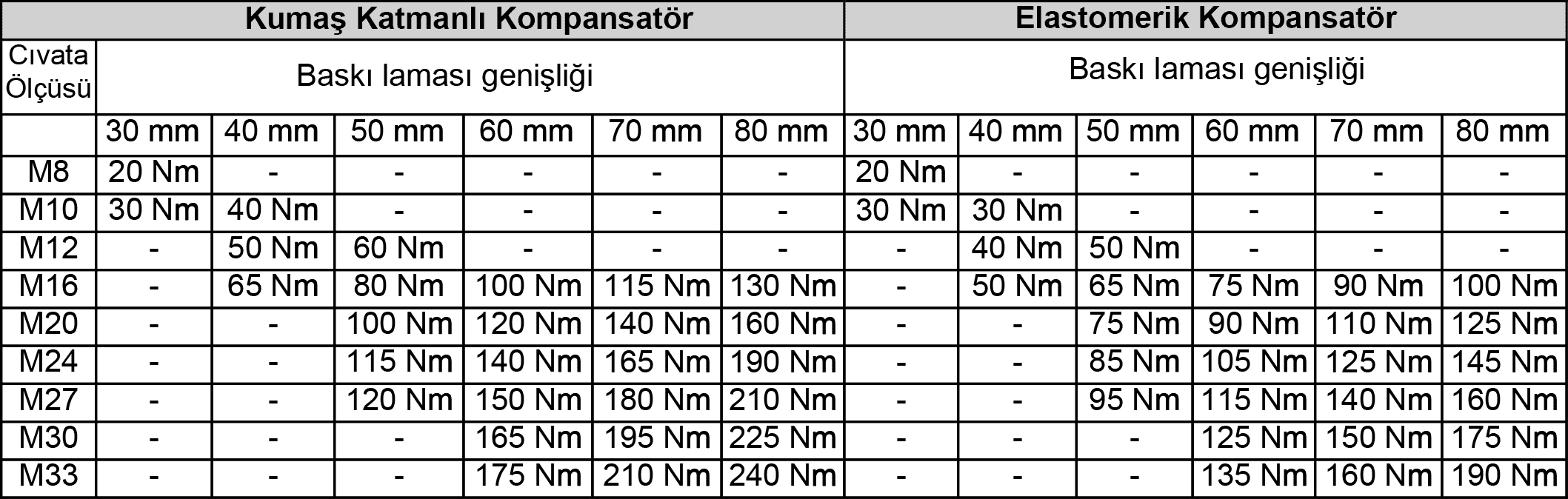
Guidelines for the dimensioning of clamp bars

The content of dust in the medium may require a specific design of the expansion joint section and the inner sleeves. In general, the following must be avoided:
• Abrasion caused by dust particles
• Sedimentation and compression of dust in the flexible element
Due to the large variety of applications and associated complexities, please refer to Metrik for specific engineering advice
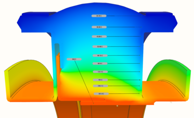
Finite Element Analysis is a computerised method for predicting how a real world structure or assembly will react to forces, heat, vibration, mechanical stress etc. in terms of whether it will break, wear out, or work as it
was intended. It is called “analysis” but in the product design cycle it is the method used to predict what will happen when the product is used.
The finite element method works by breaking a real object into many elements, and the behavior of each element is examined in the conditions in which it will operate, by a set of mathematical equations. The computer program then
adds up all the individual behaviors to predict the behavior of the complete object.
The Finite Element Method is used to predict the behavior of expansion joints with respect to the physical phenomena of:
• Heat transfer
• Mechanical stress
• Vibration
The method is used widely to verify the design of expansion joints and their structures used in gas turbine exhaust systems.
Fabric expansion joints are designed to be as leak tight as is reasonably practical. Although under laboratory conditions it is a relatively simple matter to demonstrate zero leakage, or nekal tightness, high temperature
multiple layer expansion joints should not be considered leak tight (or zero leakage) in service without first verifying site performance with extensive testing under operating conditions.
Through the careful selection and design of single layer elastomeric expansion joints, with their inherent resilience, it is much easier to ensure zero leakage systems, provided adequate attention is paid to the quality and
design of adjacent metalwork.
The vast majority of expansion joints (both single and multiple layer) can be considered leak tight through the body of the expansion joint, provided suitable materials have been specified. However, special attention should be
drawn to the general metalwork condition and design, clamping areas and their surface finishes, fixing systems such as bolts or clamps and the flange reinforcements of expansion joints. It is these areas where there is the
greatest potential for system losses.
Where practical, new metalwork supplied with the expansion joint integrally installed (an expansion joint “cartridge” system) and supplied direct from the manufacturers’ facilities will almost always ensure a much lower rate of
leakage than field splices and installation of the expansion joint to metalwork at site.
Under laboratory conditions it is possible to demonstrate flue-gas tight3 and nekal tight(4) systems, using appropriate test methods (5).
To ensure nekal tightness in service, these types of test must be carried out after installation on site.
(3) Test specification RAL TI-002 Rev. 1- 06/98 Flue-Gas Tight Fabric Expansion Joints refers to leak tight as “…no bubbles may appear in the bellows area…” and that”… the occurrence of a limited number of foam bubbles in the
clamping area and joint area of the bellows is however permitted…”.
(4) Test specification RAL TI-003 Rev. 1- 06/98 Nekal Tight Fabric Expansion Joints refers to nekal tight as no bubbles may appear in the bellows area …” and that”…this refers to both the bellows area and to the clamping
area…”.
(5) Test methods similar to DECHEMA Information Bulletin ZfP 1, annex 2 Item 2.2 “Bubble method with foaming liquid”.
Moisture within a flue duct system can have a severe, detrimental effect on the life of fabric expansion joints and therefore, should be considered carefully. At operating temperatures above the dew point of the fluid, the
moisture content will appear only when the system cools down. However, this moisture often appears as aggressive condensate and is an important factor if there are frequent thermal cycles. At operating temperatures below the dew
point, the media may contain a high degree of moisture, which can be very corrosive and damaging to the expansion joint.
Where cold ambient conditions prevail, due consideration should be given to the use of fabric expansion joints as they may give rise to condensation problems. Condensation can occur when a joint is located in a relatively low
temperature duct system. The joint will provide an internal cold face on which condensation can form if the cold face falls below dew point, giving rise to the formation of condensate which will attack the joint from the inside
causing premature failure. This can be countered by providing external insulation (note; internal insulation should be avoided). Joints should be externally insulated only on applications where the internal duct temperature is
below the maximum temperature capabilities of the constituent joint materials.
Further consideration may be given to the use of alternative materials which are less effected by acidic condensate.
Where duct or gas turbine washing is required, provision should be made for a suitable drain adjacent to the expansion joint, in order to prevent the accumulation of moisture in the expansion joint material. Where possible, the
expansion joint should not be the lowest point of the system.

Fabric expansion joints are designed to absorb movements and misalignments in ducts and pipelines. The active length of the expansion joint is that part which allows movement. It absorbs vibration and thermal movements of the
ductwork, and may or may not be the same as the flexible length, which is that part of the expansion joint between the clamping areas:
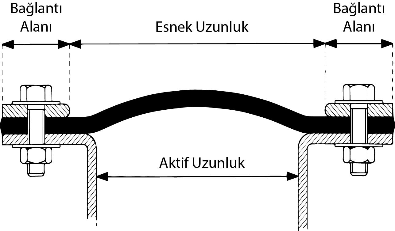
Movements are normally induced by thermal expansion of the duct plate or pipe, but other types of movements are also possible, such as wind, snow load, duct misalignment, vibration, settling and earthquake.
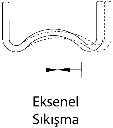
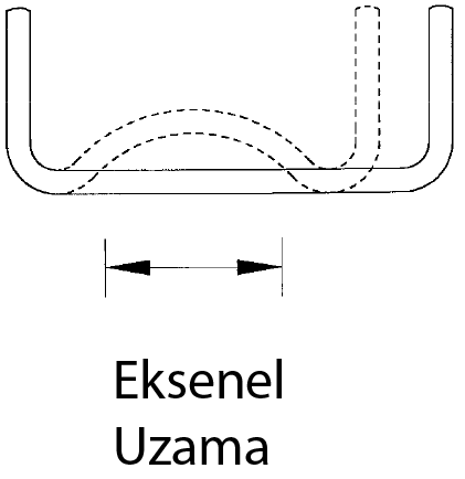
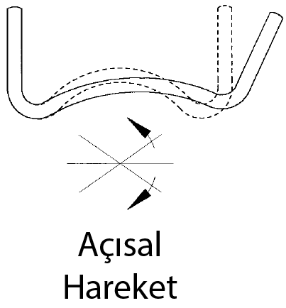
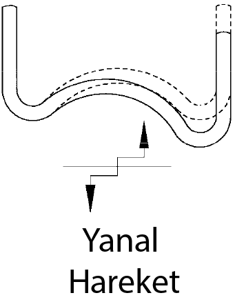
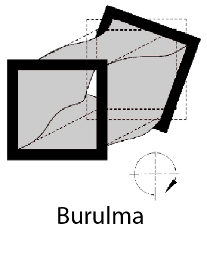
Fabric expansion joints allow 5 different movements:
Vibration and Movement Cycles
Movement caused by vibration should not be confused with movement due to thermal cycling, which is slow and relatively infrequent. Fibrous materials are poor in conditions of high frequency and amplitude. Consequently,
vibrations must be considered separately from thermal movements, to ensure correct material selection and provide suitable design recommendations.
In-duct noise breakout may be an important design consideration under certain circumstances and can be reduced by acoustic treatment of the duct. Fabric expansion joints may be the primary source of noise breakout in a duct system, and an internal acoustic bolster may be incorporated into the design to reduce such noise. The bolster would normally be manufactured from insulation material encased in a temperature resistant woven fabric or wire mesh (or both) and located between the joint and the internal flow sleeve. The design of the internal flow sleeve(s) can also play an important part in the acoustic performance of a joint.
The operating pressure in a system is a crucial factor affecting the design of fabric expansion joints. The very flexible nature of the materials brings several design issues which must be addressed. Although maximum operating
pressures in duct systems are low by comparison with pipeline systems, wide variations of pressure, such as a change from positive to negative, or short-term peak pressures can occur. Such variations should be reflected in the
design pressure specified, and the measure of gas tightness expected by the customer. Care in the choice and construction of materials must allow for:
• Containment of the stated design pressure under all conditions of movement and temperature, without over-stressing any of the expansion joint element
• Changes from positive to negative pressure which could entrap materials under compression, or cause them to be in contact with sharp or hot parts of a duct
• High positive pressure and compression allowing materials to abrade on bolt heads of clamp flanges
• Changes in pressure causing significant air spaces between layers of composite joint materials, which could allow circulation of hot gas
• Pressure surges occurring as a result of system operation
Pulsation
Pressure pulsation in a duct or pipeline can be detrimental to a fabric expansion joint, particularly those manufactured from plies of woven glass-cloth or ceramics. Rapid variation in pressure causes fatigue of the fibers and
can lead to premature failure of the expansion joint. Caution is required when designing expansion joints for combustion engine exhaust systems to ensure that the joint is not fitted too close to the engine. A sufficient
distance is required to allow the pressure fluctuations to subside.
Flutter
Flutter can be induced by fans, particularly where the system is unbalanced, and the materials used for expansion joints adjoining fans must be selected with this in mind. To overcome flutter of the joint materials, which could
lead to premature failure, the materials must be of sufficient thickness and density to damp out the oscillations. Reinforced elastomeric materials are commonly specified for expansion joints fitted to the fan inlet or
outlet.
Flutter in expansion joint seals can be induced by high gas velocity but is usually eliminated by careful design of a suitable flow liner attached to the duct or joint frame. The inclusion of a bolster can help to minimize
flutter.
Operating temperature
The operating temperature is the normal temperature of the media within the flue duct system under operation. Normally indicated in degrees C as design or maximum operating temperature.
Thermal cycles
The definition of a thermal cycle is when the temperature in a flue duct system moves from ambient to full operating temperature and then returns to ambient. The number of thermal cycles is often used when calculating the life
expectancy of steel frames for gas turbine exhaust systems or when considering the number of times moisture could appear in the system on cool down.
Excursion temperature
Occasionally, flue duct systems will have an upset condition or excursion. This is a situation when, for a short period of time, the temperature in the system increases above normal operating temperature. The expansion joint
designer must consider this upset condition for duration and temperature when making material selection.
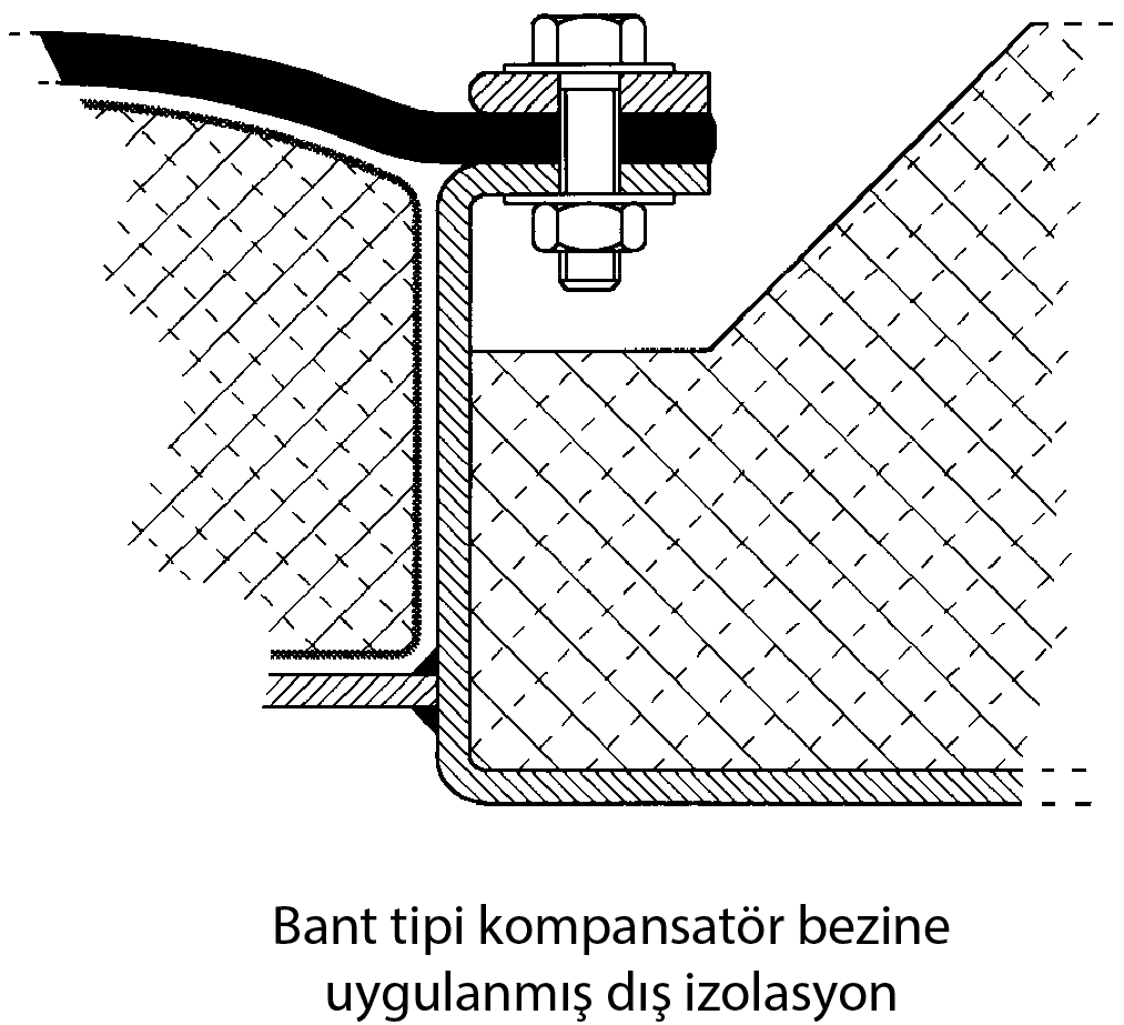
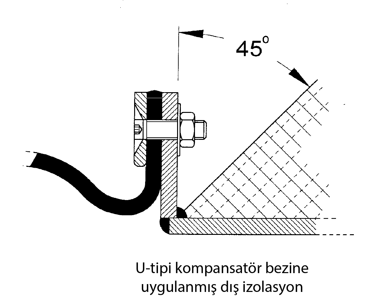
External insulation
External insulation should not cover a fabric expansion joint, except when it is part of the joint design to avoid condensation below dew point. The termination of duct insulation is critical to the airflow over the outer cover
and in general should be chamfered back at an angle of not less than 45°. For extremely hot applications, the insulation termination must be carefully designed to minimize stress in metal frames and overheating in the clamping
area.
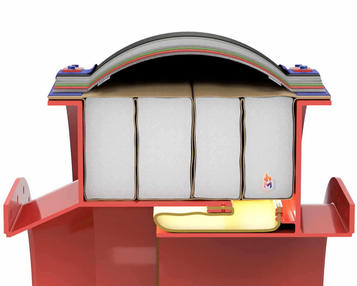
This is part of an expansion joint assembly incorporating bulk materials, often in the form of an encased pillow, which can be used to fill the cavity between the flexible element and the internal sleeve.
The primary reasons for their inclusion in an expansion joint design are:
• To provide additional thermal protection for the expansion joint, using bulk insulation materials with good thermal properties.
• To prevent the ingress of solid particles into the cavity of the expansion joint. In systems where the media may have a heavy dust content there are two main challenges.
Firstly, the potential for abrasive particles causing damage and premature failure to the flexible element.
Secondly, particles may accumulate in the cavity, becoming compacted and preventing compressive movements in the system.
• To improve the acoustic performance of the expansion joint system using bulk materials with good acoustic attenuation or absorption properties.
• To provide support to the flexible element and minimize the effects of pulsations or “flutter” by preventing the onward transmission of these variations to the flexible element.
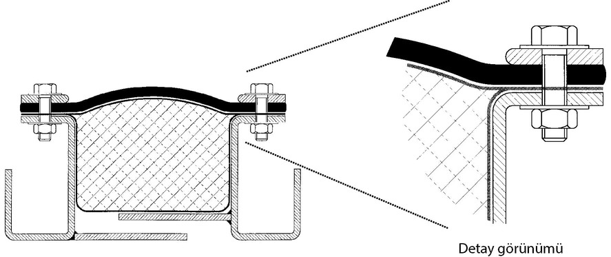
İzolasyon Yastığı Konstrüksiyonları
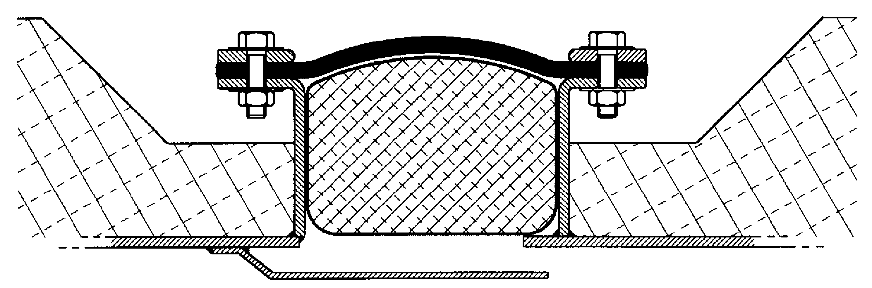
A. Flanged Type
This construction maintains the position of the insulation bolster and provides the highest level of heat resistance. In this system, the flanges of the bolster are bolted between the compensator cloth and the metal flanges.
Thus, the bolster acts together with the expansion joint, protecting the critical layers of expansion joint against the corrosive effects such as heat and abrasive dust.
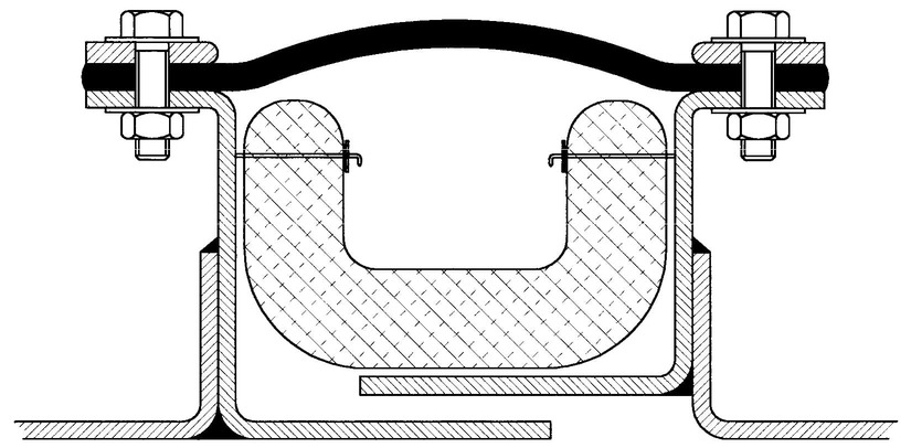
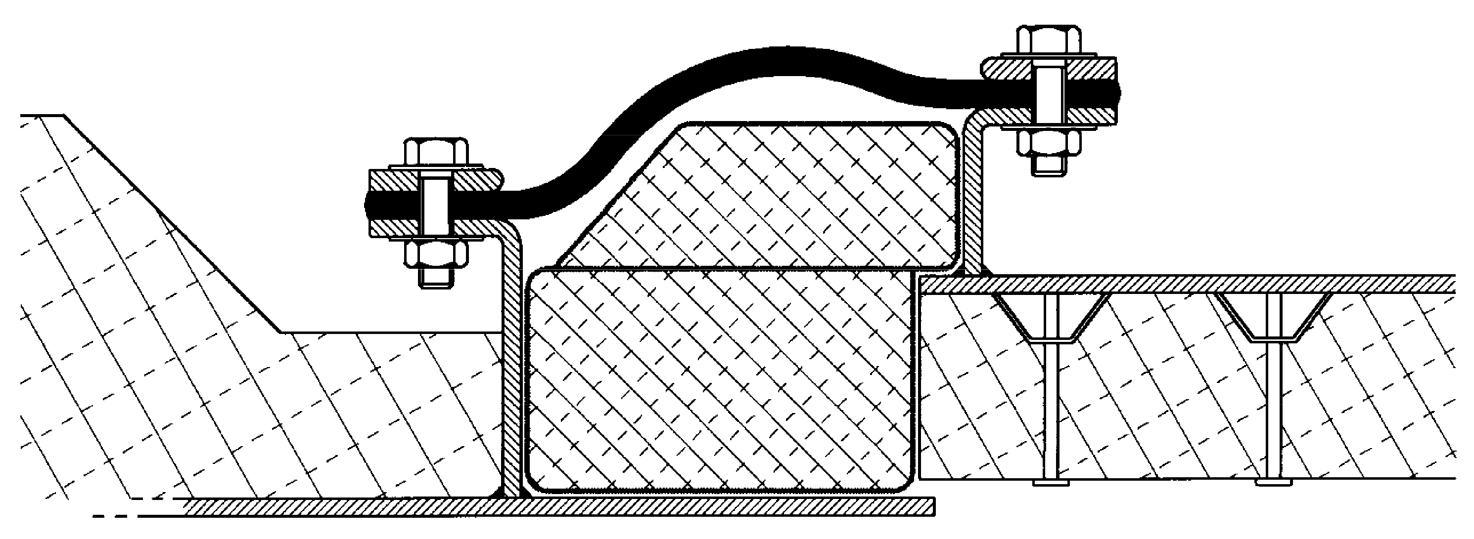
B. Pinned Type
In this system, the isolation pad is fixed with the help of metal parts isolation pins so that it can move with the compensator cloth. Fixing can be done inside the channel edges or on the baffle plates.
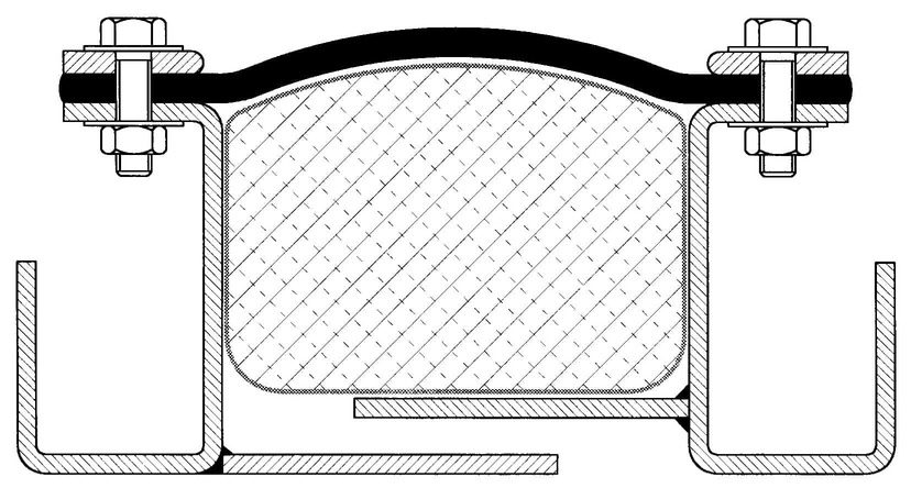
C. Block Type
Block type insulation pads, which offer the most practical manufacturing and assembly possibilities, are placed between the compensator cloth and the flow sleeve.
Design of internal flow sleeves (also known as flow liners) is strongly associated with the expansion joint frame design, and the liner is often formed by part of the duct itself. Many variations are possible, but a range of
common types is defined below.
The shape of an internal flow sleeve is an important design aspect, to ensure that the movement is not restricted. The main function is to exclude high velocity gases or particles, so preventing the erosion of seal or bolster
materials. Other important considerations are:
• The thickness of material in relation to the possibility of erosion,
• The length of each section of flow sleeve, bearing in mind expansion and deformation due to temperature,
• Requirements for duct washing, and the need to protect seals and bolsters
• Flow sleeves are normally stitch-welded to the frame
Internal flow sleeves must be designed so that they will not entrap dust or condensation. Please consult Metrik for specific advice.
Simple to install in existing channel or angle flanged frames. The overlap allows the use of secondary dust seals when required.
Care is needed with this type of flow sleeve to ensure there is no mechanical interference with the seal materials. Generally used only where movement is limited.

The frame design and movement requirements govern the shape of this flow sleeve. The taper (also known as "step" or "joggle") is usually limited to that required for lateral movement, to ensure that any insulation bolster is fully retained.
This can be used when there is a need to maintain the minimum gap between flow sleeve halves with high lateral joint movements. The floating section is retained at intervals by angles or pins to allow free movement in the required plane
Particle Barrier is used in systems with very high solid particle content to minimize the entry of particles carried in the environment into the expansion joint frame
In this way, it is aimed that the compensator works for a long time.
Please consult us for details.
Particle Discharge Pipe is used for automatic or manual evacuation of particles filled into the compensator cavity in systems with very high solid particle content.
In this way, it is aimed that the compensator works for a long time.
Please consult us for details.
The Particle Deflector is an L-profile metal component located just above the diverter plate, used in the presence of upstream fluid with a very high solid particle content.
It prevents the particles falling down due to gravity or turbulent currents from accumulating inside the guide plate.
In this way, it is aimed that the compensator works for a long time.
Please consult us for details.
A drain pipe made of stainless steel or PTFE material is attached to the part of the compensator closest to the ground in order to drain the corrosive acidic condensate that may damage the expansion joint.
However, the use of condensation barrier type guiding sheet will largely prevent the condensation that will form from filling into the expansion joint frame
In this way, it is aimed that the compensator works for a long time.
Please consult us for details.
A simple frame attachment for existing ductwork. For circular ducts the angles would be rolled toe-in in suitable lengths for welding. For rectangular ducts a fabricated, radiused corner would be used to join the straight lengths. If rolled steel angle is used, tapered washers should be used under the flange.

There are several methods of clamping fabric expansion joints, some of the most common are detailed below:
| Expansion Joint Type | Clamping Device | Duct Cross Section | Duct Size | Operating Pressure | Cost of Clamping Method | Comments |
|---|---|---|---|---|---|---|
| Belt | Word drive | Circular | Small | Low | Low | Fast installation |
| T-Bolt | Circular | Small - Large | Low | Low | Fast installation | |
| Clamp Bar | Circular / Rectangular | Small - Large | Low - High | Medium | High temperature capability | |
| External Clamp | Circular / Rectangular | Small - Large | Low | High | Moderate temperature capability | |
| Flanged | Clamp Bar | Circular / Rectangular | Small - Large | Small - Large | Medium | Moderate temperature capability |
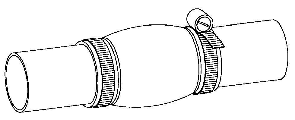
Worm drive ("Jubilee clip") or bolt type (T-bolt) clamp bands
Used on smaller diameter circular belt type fabric expansion joints, and usually manufactured from stainless steel strip
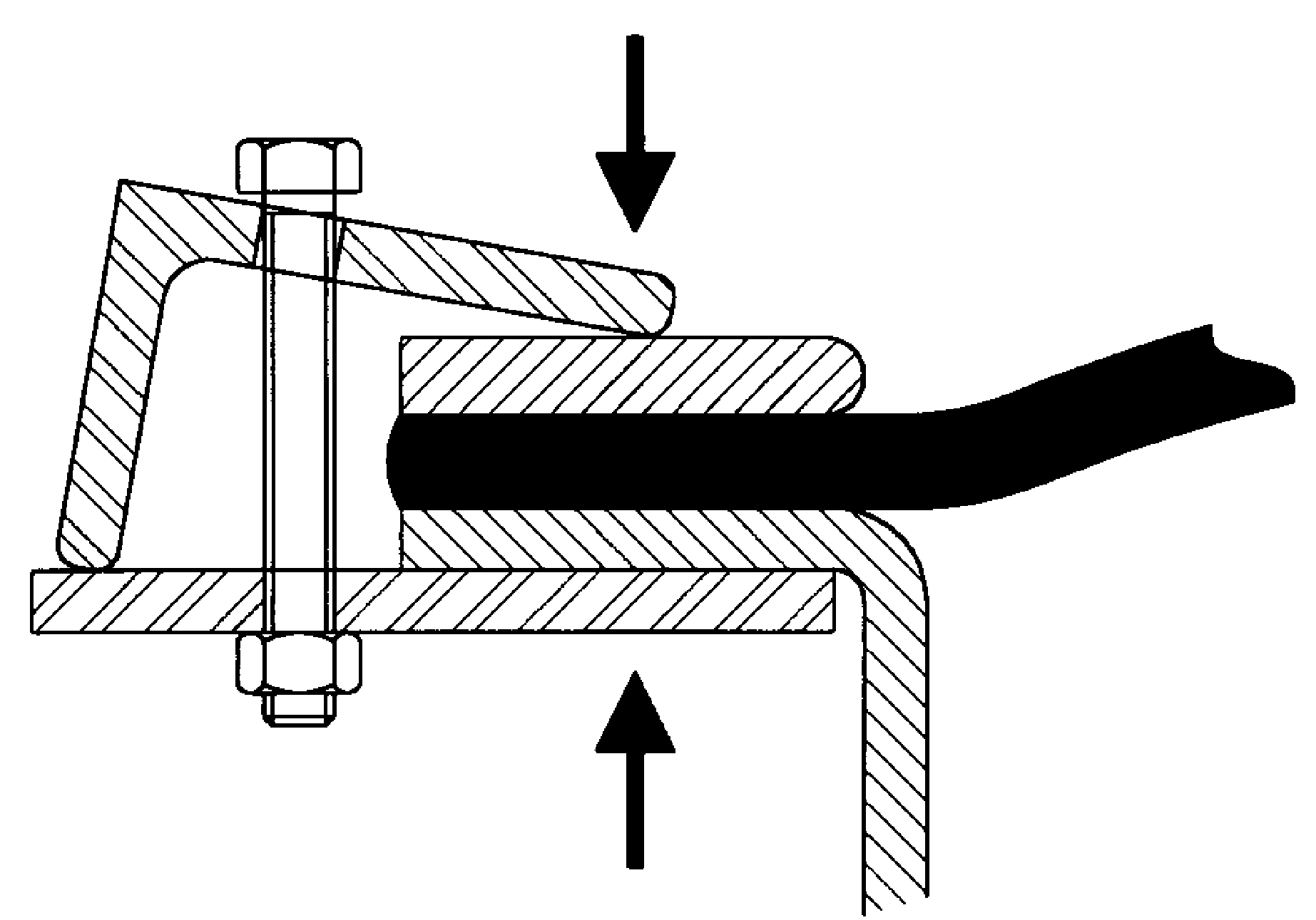
Clamp bars used with fixings (bolts, nuts, washers)
Clamping bars assembled using bolts, nuts and washers allow the expansion joint fabric to work under high temperature and high pressure.
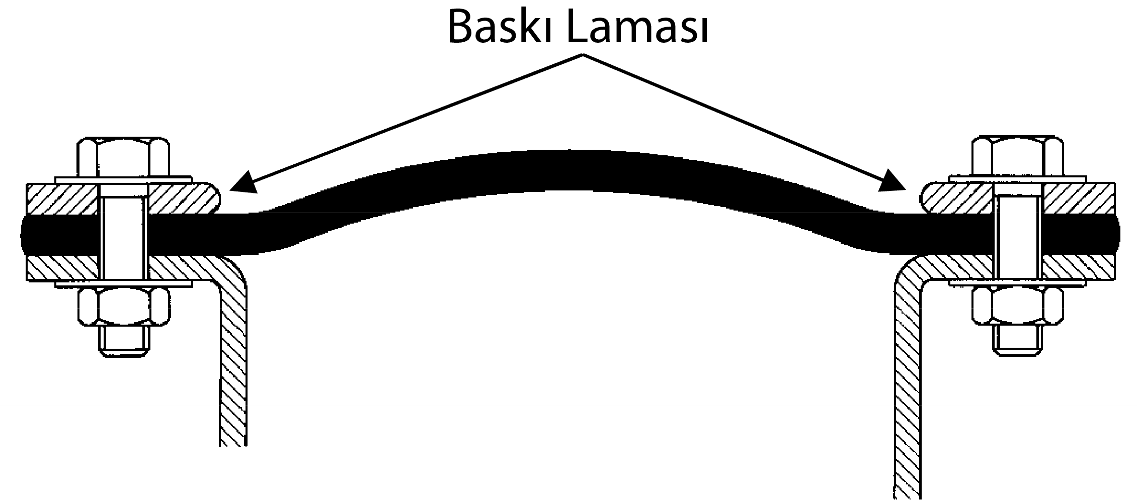
Please note that belleville (cone) washers are often used to maintain bolt loading:
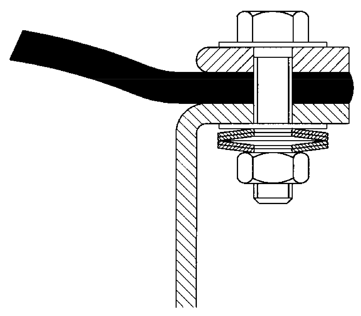
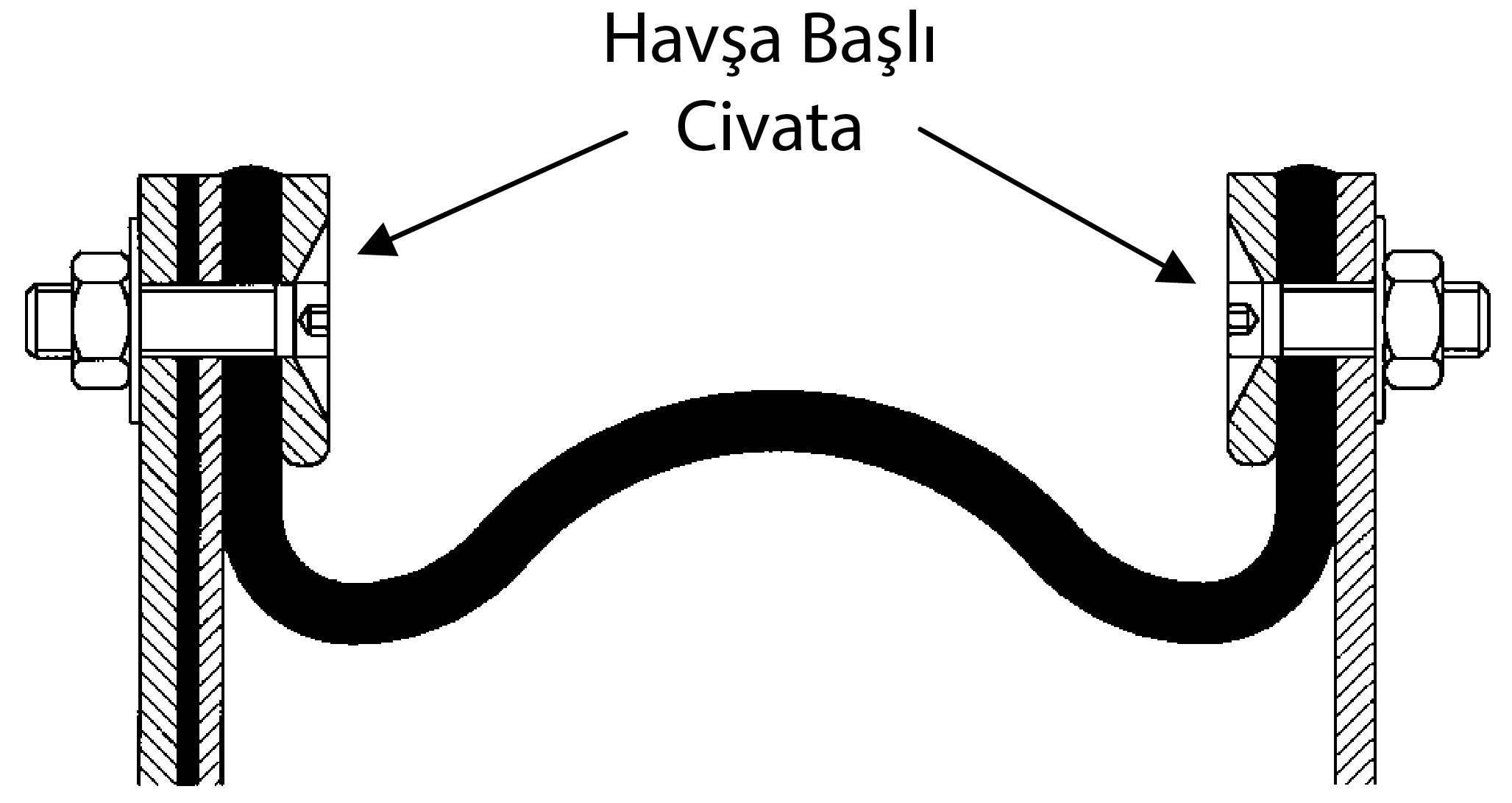
Note: In those cases where there is positive pressure combined with high axial movement, countersunk fixings should be used to prevent bolt heads damaging the outer cover of the expansion joint:
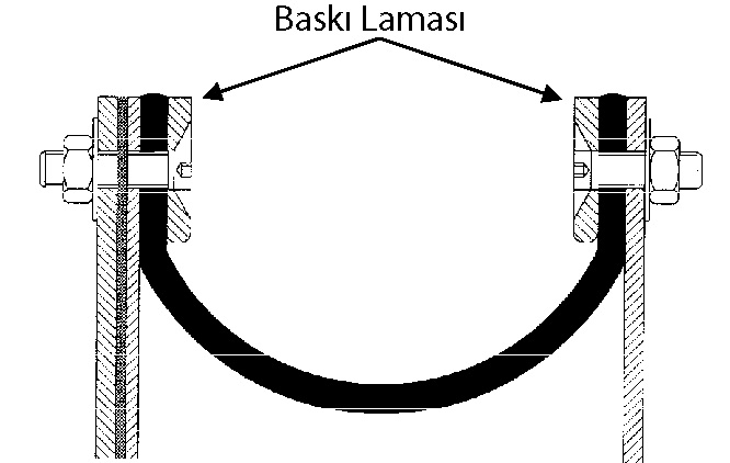
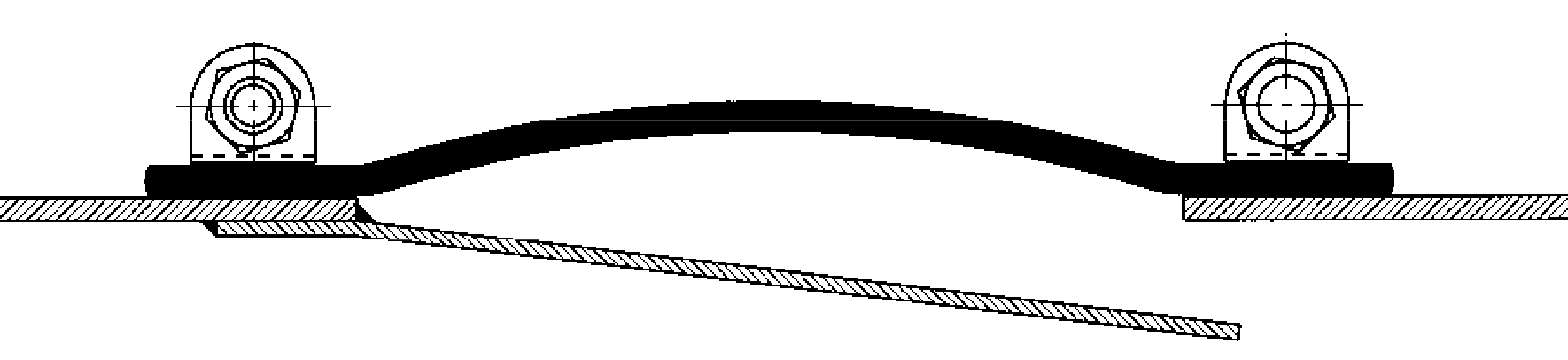
Clamp bars used with external clamps
his connection system, which is generally used in belt-type compensator fabrics, is an alternative solution for environments where the previous connection system is not suitable.
Effective sealing is dependent upon the design of the frames to which the flexible element is attached. Many variations of frame are possible, depending on the structure to which the expansion joints are attached, but there are
some basic configurations which cover the majority of applications.
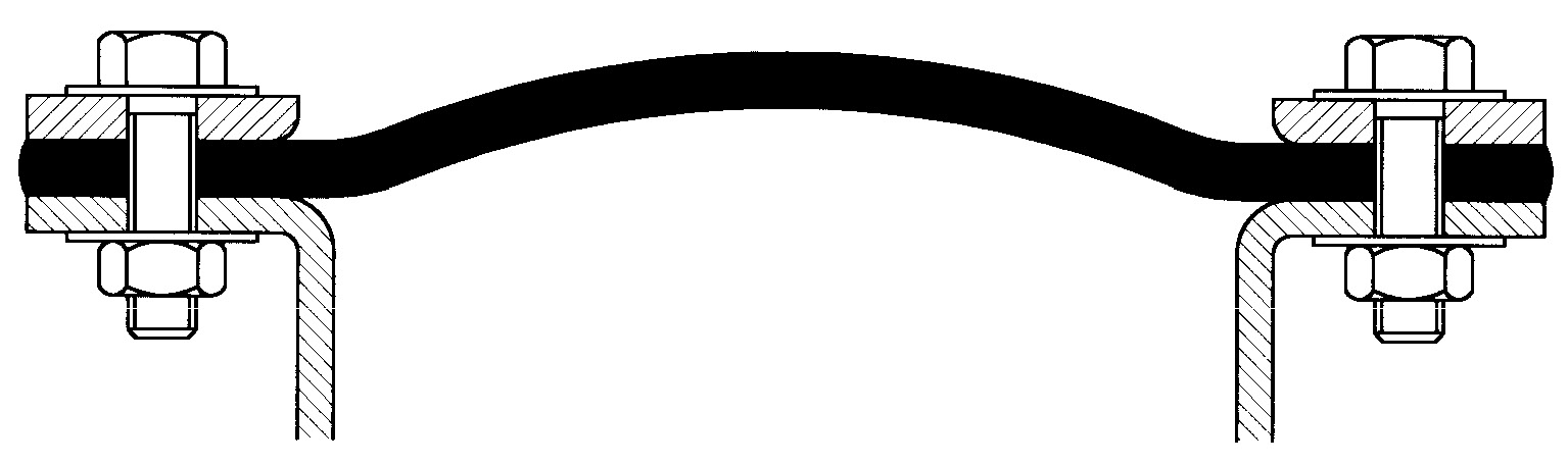
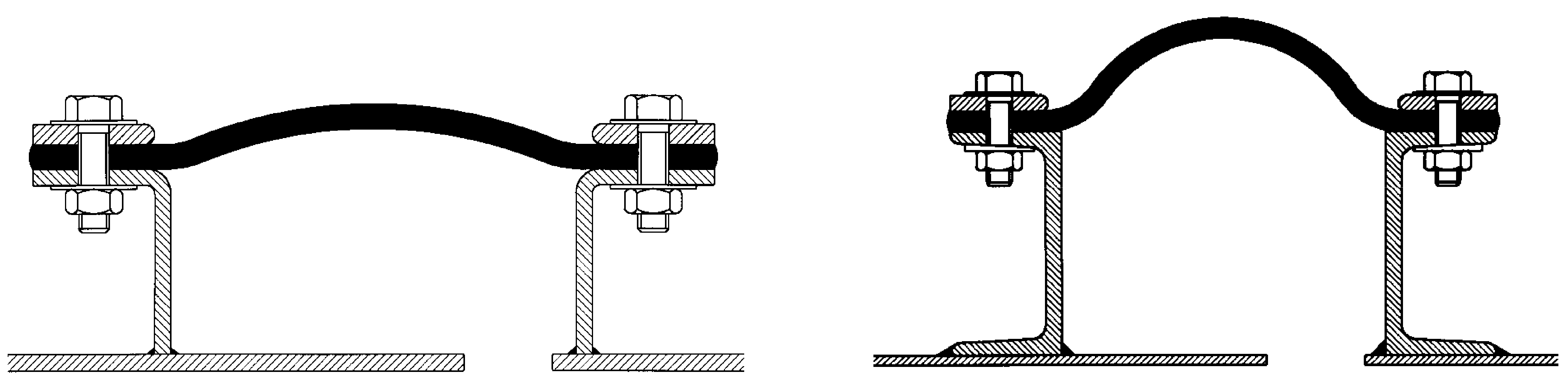
1) The belt type expansion joint
provides the most effective joint from both a manufacture and attachment point of view. In these joints, the materials are subject to minimum stress until moved under operating conditions, and the airflow over the seal outer
cover is largely uninterrupted. Frames for belt type expansion joints can be slightly more complex than for flanged expansion joints, but this is offset by the ease of repair or replacement of the flexible element. In general,
these provide a longer life than flanged type expansion joints.
Can be used effectively only for circular ducts operating at low pressure. For large diameters, clamp bands must be in several sections, in order to ensure even clamping pressure.
A simple frame attachment for existing ductwork. For circular ducts the angles would be rolled toe-in in suitable lengths for welding. For rectangular ducts a fabricated, radiused corner would be used to join the straight lengths. If rolled steel angle is used, tapered washers should be used under the flange.
This frame is commonly used when complete expansion joint assemblies are required, often for installation in new build projects, with the added advantage of simplified installation. These designs give freedom to locate the expansion joints most conveniently. Also, the frame design can be altered to accommodate varying thicknesses of bolster and the size of the duct flanges.
Offer the duct designer the simplest methods of attachment, but the nature of their construction restricts their use at higher temperatures. For multi-layer expansion joints where there are more than 3 or 4 plies of material, the fabrication of the flange restricts the available movement, and necessitates deeper flanges and wider breach opening. The flange configuration does allow designs for large axial movements and high negative pressures.
Where internal flow sleeves are fitted in this configuration they must be clear of the seal material, especially for rectangular joints at the corners.
For high values of negative pressure it is essential to prevent sharp angles in the flexible element. The type of expansion joint which may be used with this frame design has some temperature limitations, because of the restricted airflow over the seal surface.
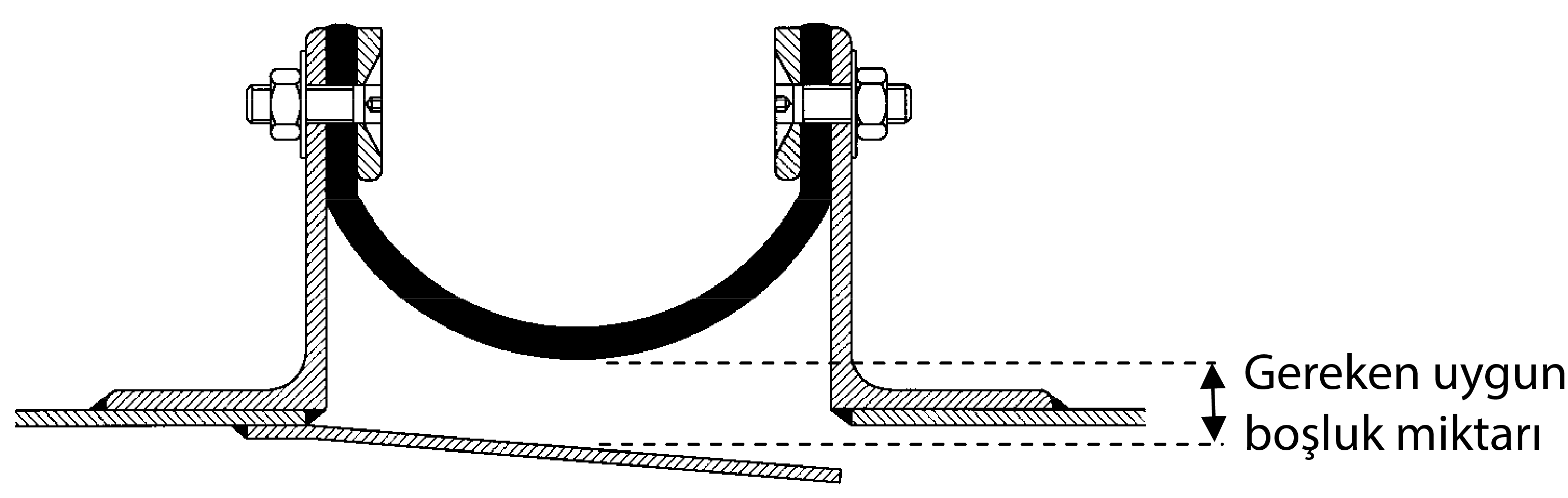
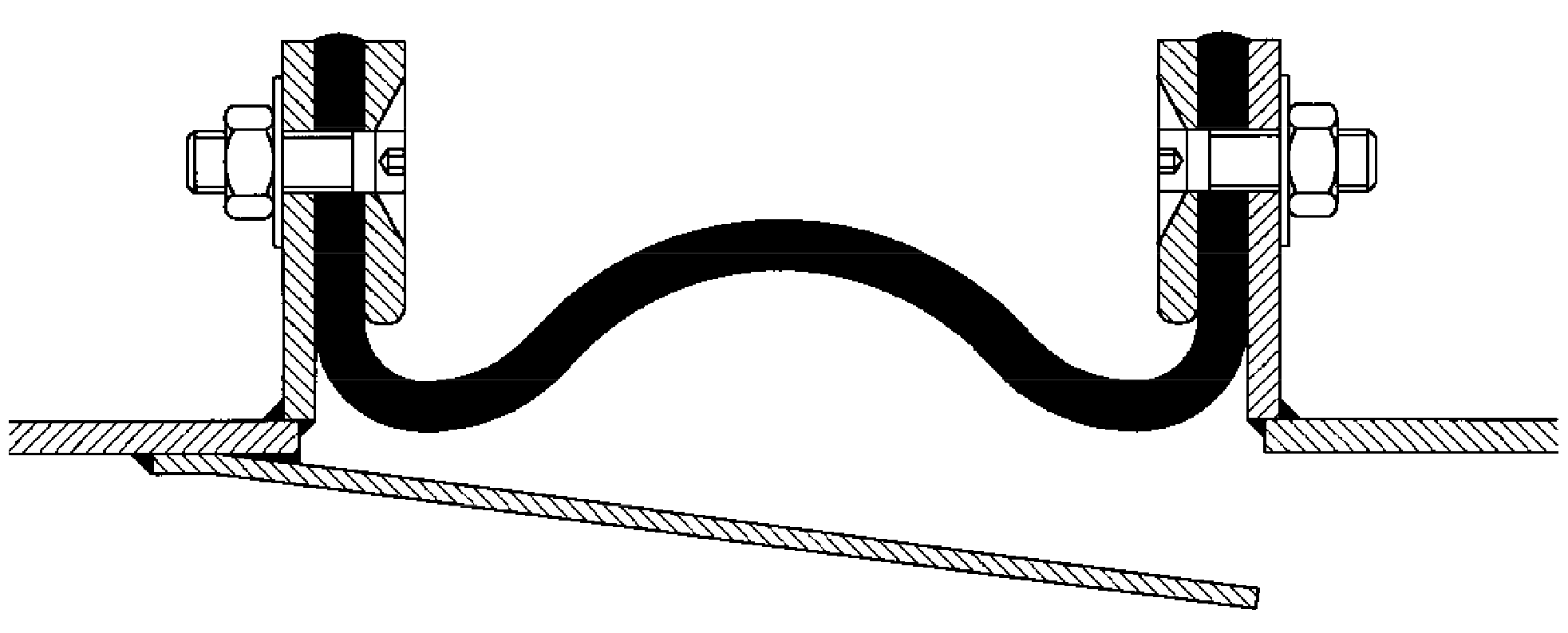
in gas turbine systems, and other high temperature applications, expansion joints are often located at the point where the duct insulation changes from internal to external or vice versa. This provides a convenient terminal point for the duct designer, as the change in duct size and duct material can be made over the length of the expansion joint. The support of the internal insulation requires careful design, and sometimes the seal must be conical or tapered to keep the frame design within stress limits. A few examples (using belt type expansion joints) follow:
The flexible element of the expansion joint assembly performs the most important function in that it absorbs or allows the movement for which the joint is designed.
This movement can be axial, lateral, angular or any combination of them. For rectangular expansion joints, the corners represent the greatest challenge and need careful design consideration.
Without costly moulding techniques, the corners of U-type expansion joints are generally not radiused, and therefore movement is limited by the strain on the material imposed by creasing in the axial plane, and stretching under
lateral movement.
Elastomeric joints with moulded corners overcome some of these stresses, but composite joints need careful design to avoid early failure of the fabric element.
Belt type expansion joints with radiussed corners offer the best solution for rectangular assemblies. The expansion joint material can move in a similar way to circular expansion joints, and where movements are high, the corner
can be tailored to include additional material for both axial and lateral movement.
The corner radius is also advantageous in the design of hot expansion joint frames, which are subject to high thermal stresses.
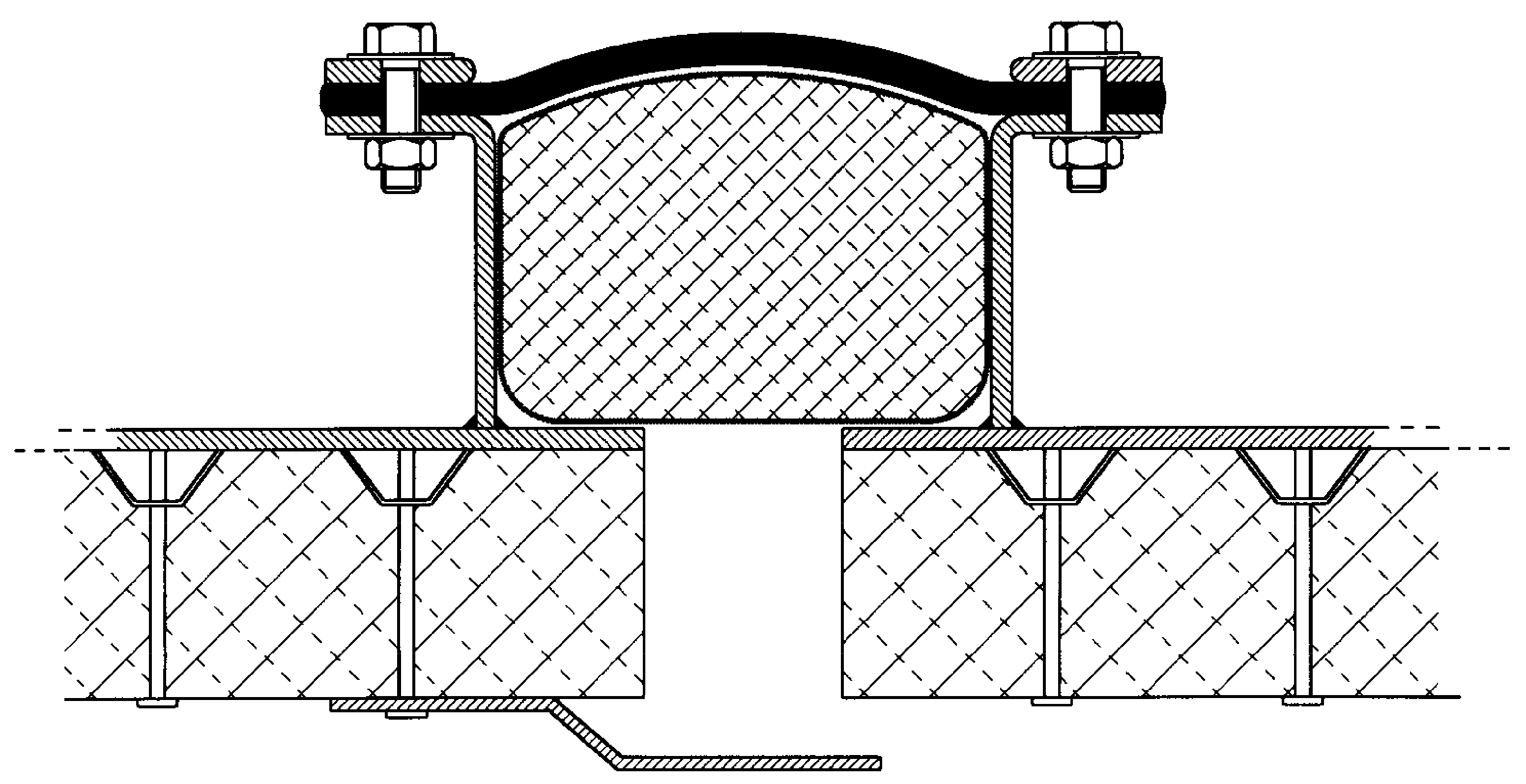
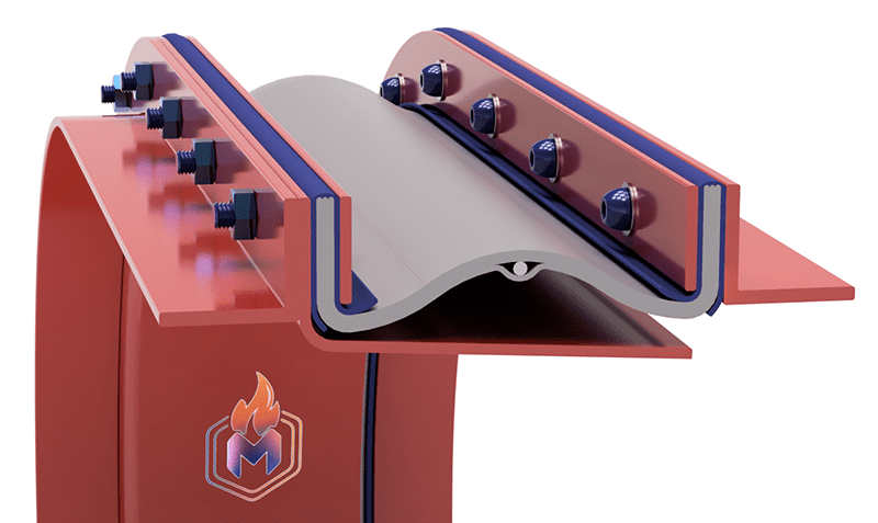
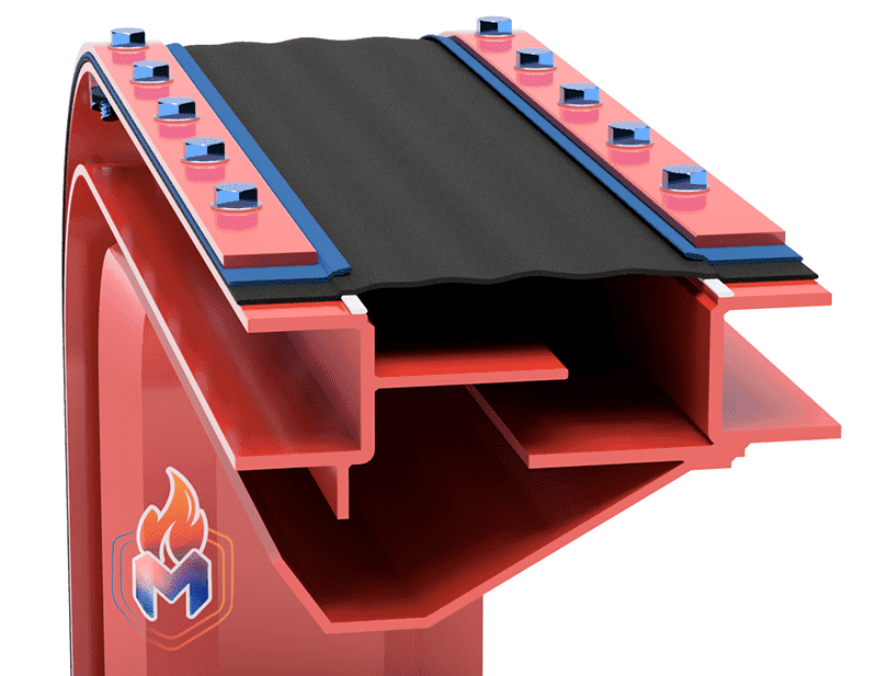
Fanflex compensators dampen thermal expansion, vibrations and misalignments in piping and duct systems in low temperature regions.
- Single or multi-layer structure
- Absorbs movement in many axes simultaneously
- Use in dry and wet environments
- Metal ring support for high pressure (+/-) protection
- Optional metal flange or clamp production
- Operating temperature range: -50 °C / +300 °C
- Operating pressure range: -0,25 bar / +0,25 bar
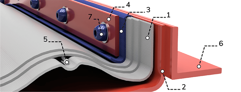
- 1- Expansion Joint Fabric
- 2- Detachable Liner*
- 3- Flange reinforcement
- 4- Clamping Bar
- 5- Pressure Ring*
- 6- Connection Flange
- 7- Round Head Bolt*
* Optional
ChemFlex expansion joints dampen thermal expansion,
vibrations and misalignments in pipe and duct systems containing aggressive chemicals.
- Single layer structure
- Absorbs movement in many axes simultaneously
- Suitable for use in dry and wet environments
- High resistance to acids
- Optional metal flange or clamp production
- Operating temperature range: -35 °C / +425°C
- Working pressure range: -0.35 bar / +0.35 bar
- 1- Expansion Joint Fabric
- 2- Condesation Barrier*
- 3- Single Face Flange Reinforcement
- 4- Clamping Bar
- 5- Sealing Gasket*
- 6- Welding End
- 7- Internal Liner*
* Optional
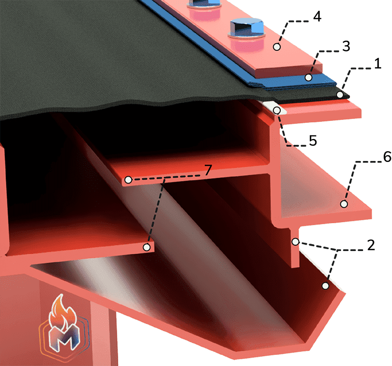
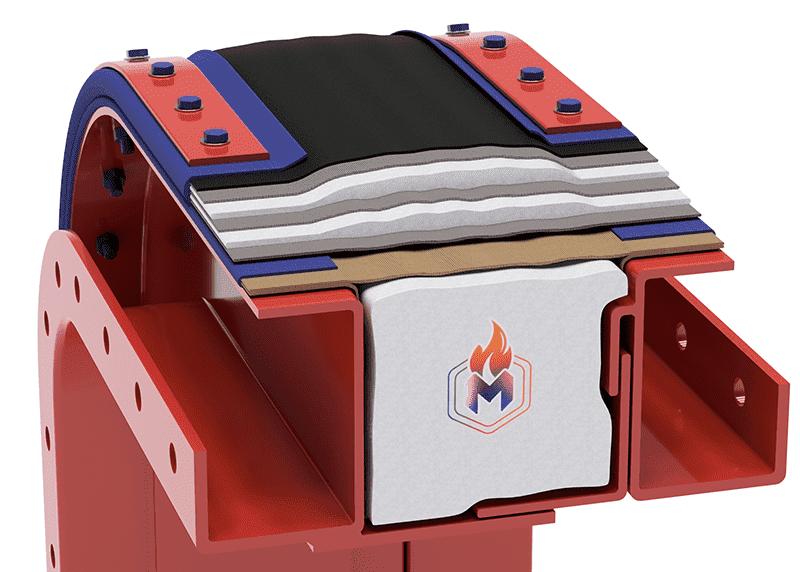
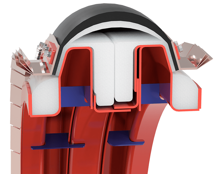
MultiFlex compensators absorb thermal expansion and misalignment in piping
and duct systems in dry and medium temperature regions.
- Multi-layered structure
- Absorbs movement in many axes simultaneously
- Suitable for use in dry environments
- Low acid resistance
- Optional steel frame can be manufactured
- Operating temperature range: -50 °C / +575 °C
- Working pressure range: -0.25 bar / +0.25 bar
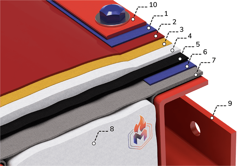
- 1- Flange Reinforcement
- 2- Outer Layer
- 3- Sealing Layer
- 4- Heat Insulation Layer
- 5- Mechanical Strength Layer
- 6- Insulation Bolster Flange Reinforcement
- 7- Insulation Bolster Outer Layer
- 8- Insulation Bolster Fiber
- 9- Connection Flange
- 10- Clamping Bar
UltraFlex compensators absorb thermal expansion and misalignment in
piping and duct systems in dry and medium temperature regions.
- Multi-layered structure
- Absorbs movement in many axes simultaneously
- Suitable for use in dry environments
- Low acid resistance
- Optional steel frame can be manufactured
- Operating temperature range: -50 °C / +800 °C
- Working pressure range: -0.30 bar / +0.30 bar
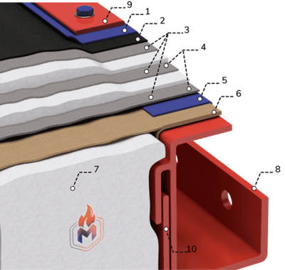
- 1- Flange Reinforcement
- 2- Outer Layer
- 3- Mechanical Strength Layer
- 4- Heat Insulation Layer
- 5- Insulation Bolster Flange Reinforcement
- 6- Insulation Bolster Outer Layer
- 7- Insulation Bolster Fiber
- 8- Connection Flange
- 9- Clamping Bar
- 10- Floating Liner*
* Optional
ArmiFlex compensators safely absorb thermal expansion and slippage of piping and duct systems in dry,
high temperature and high flow areas. It has a high elongation capacity thanks to its special curved structure.
- Multi-layered structure
- Absorbs movement in many axes simultaneously
- Suitable for use in dry environments
- Specially designed for high elongation movement
- High acid resistance
- Operating temperature range: -50 °C / +850 °C
- Working pressure range: -0.35 bar / +0.40 bar
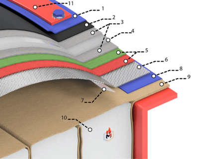
- 1- Flange Reinforcement
- 2- Outer Layer
- 3- Mechanical Strength Layer
- 4- Heat Insulation Layer
- 5- High Temperature Resistant Layer
- 6- Stainless Knitted Wire
- 7- Steel Band Reinforcement
- 8- Insulation Bolster Flange Reinforcement
- 9- Insulation Bolster Outer Fabric
- 10- Insulation Bolster Filler Fiber
- 11- Clamping Bar
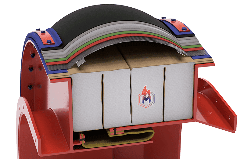
There are three basic types of turbine compensators: hot to hot, hot to cold, and cold to cold. Each type is determined by the operating conditions of
the place where it will be installed, and each requires specific construction and design materials.
There are many designs produced by Metrik Industrial for turbine inlets and
turbine exhaust compensators. Below are some typical examples showing the basic setup.
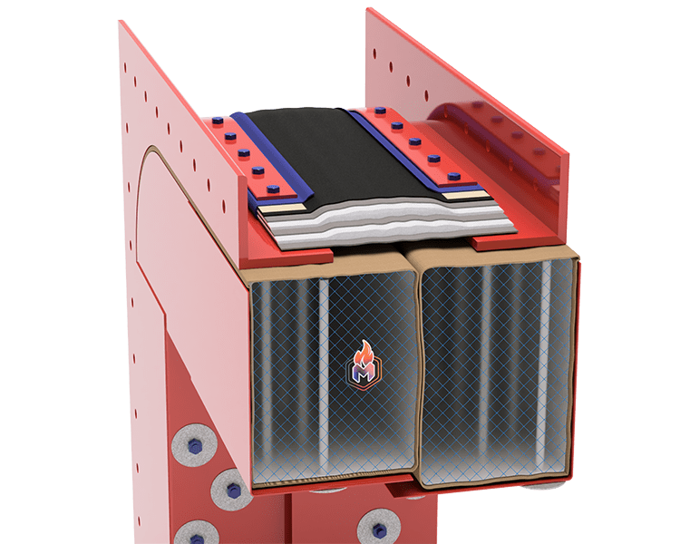
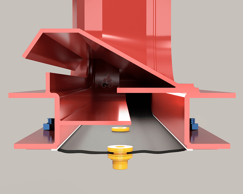
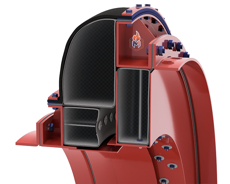
Cold to Cold gas turbine compensator
configurations are used in regions where both connecting
flanges have internal insulation.
For mounting the slotted guide plates, it uses studs welded to the connection flange,
so that the hanging guide plates move freely in the direction and amount allowed by the
slot holes with the temperature increase.
In this model, no part of the compensator carcass is directly exposed to the hot gas flow.
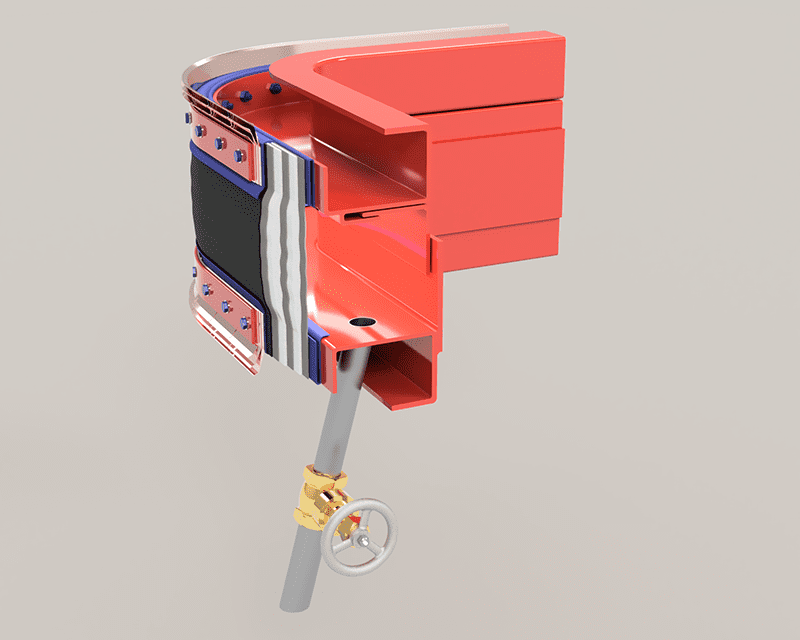
Hot to Cold gas turbine compensator configurations are used
in regions where one connecting flange operates at exhaust gas temperature
and the other connecting flange has internal insulation.
The compensator pad on the non-insulated flange side is fixed to the
anchor pins with insulating washers and welded to the steerer body.
On the internally insulated flange side, it uses studs welded to the
connection flange for the mounting of slotted guide plates, so that
the hanging guide plates move freely in the direction and amount
allowed by the slot holes with the increase in temperature.
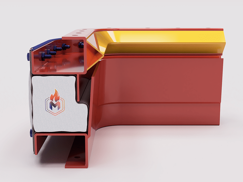
Hot to Hot gas turbine compensator configurations
are used in areas where both connecting flanges operate at exhaust gas temperature.
Special carcass design offers a very high number of cycles
compared to conventional compensator carcasses.